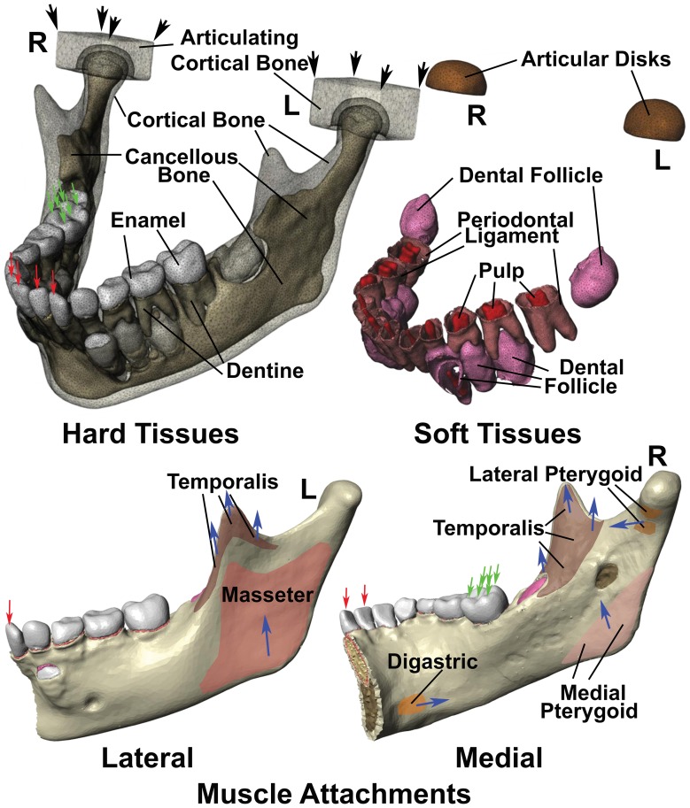
Figure 3. Diagrams illustrating the finite element model constructed in this study.
Illustrated are the boundary conditions, as well as the muscle attachments on the lateral left and medial right surfaces of the mandible, while left (L) and right (R) joints are indicated respectively. Hard tissues modelled included cortical bone, cancellous bone, enamel and dentine. Two solid blocks with the properties of cortical bone were modelled in replacement of the base of skull. Soft tissues included dental follicle, periodontal ligaments and dental pulps, while articular disk material with the physical properties of cartilage were modelled between the mandible and articulating cortical bone blocks. The lateral surface of the mandible had only temporalis and masseter muscle attachments, while attachments for the digastric, temporalis, lateral pterygoid and medial pterygoid muscles were modelled on the medial surface. The direction of muscle force is indicated with blue arrows. The articulating cortical bone blocks were assumed fastened at the corners indicated with black arrows, while in the case of incisor biting, single fixed points were assumed at all four incisor edges (red arrows), with muscle traction generating strain within the constructed model was applied. Right molar bite force was also modelled by fixing 6 points on the outer and upper surfaces of the right first molar as indicated (green arrows), and applying muscle traction.

