Fig. 1.
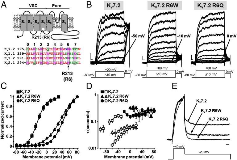
Functional properties of homomeric KV7.2, KV7.2 R6W, and KV7.2 R6Q channels. (A) (Upper) Topological representation of a Kv7.2 subunit. The R213 (R6) residue is highlighted. (Lower) Sequence alignment of the S4 segments of the indicated Kv subunits (www.ebi.ac.uk/Tools/psa/). Residues are colored according to the following scheme: magenta, basic; blue, acid; red, nonpolar; and green, polar. (B) Macroscopic currents from KV7.2, KV7.2 R6W, and KV7.2 R6Q channels, in response to the indicated voltage protocols. Current scale, 100 pA; time scale, 0.1 s. The arrows indicate the threshold voltage for current activation. (C) Conductance/voltage curves. Continuous lines are Boltzmann fits to the experimental data. (D) Time constants for ionic current activation (weighed average of τf and τs; filled symbols) and deactivation (empty symbols) for the indicated channels (n = 4–9). (E) Normalized and superimposed current traces from KV7.2, KV7.2 R6W, and KV7.2 R6Q channels. Current scale, 100 pA; time scale, 100 ms.

