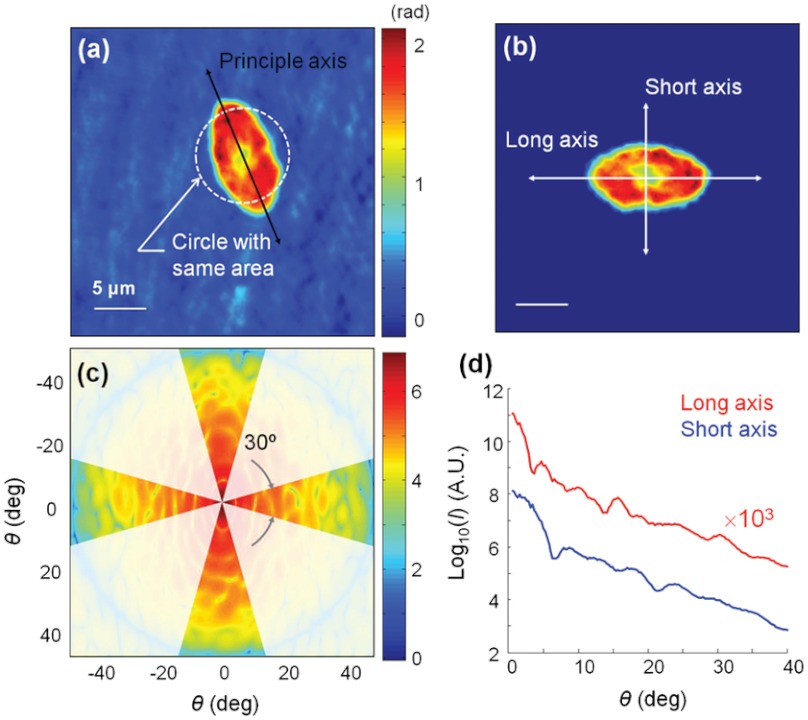
Fig. 2.
(a) Phase image of a typical sickle RBC. (b) The long axis is rotated to be aligned with the horizontal axis and the center of mass of the sickle RBC is moved to the center. (c) The retrieved light scattering pattern with the denoted angle ranges for the long and short axes. (d) Light intensity-scattering patterns with respect to the long and short axes of the RBC.

