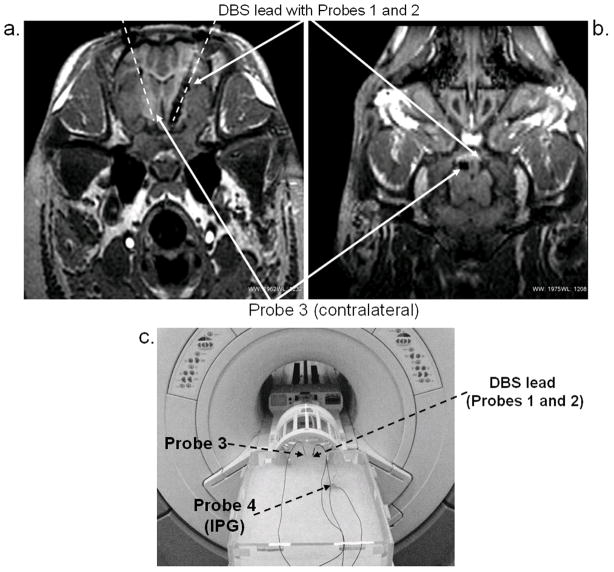
Figure 2.
Experimental setup: (a) Axial MR image of pig’s head showing orientation and position of DBS and temperature probes (Probes 1, 2, and 3) within the STN. Overlaying dashed lines provide visual guidance. (b) Coronal MR image of the pig’s head showing probe positions (c) Measurements in the head-and-trunk phantom. DBS and IPG were positioned inside the phantom in locations approximating surgical placements inside the animal.

