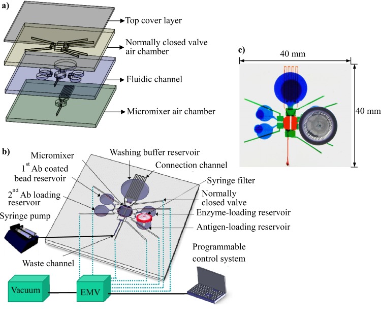
Figure 1.
(a) Exploded view of the proposed microfluidic chip. Four layers of PDMS were used to construct the negative-pressure-driven microfluidic chip. The bottom layer was an air chamber layer for the actuation of a pneumatic micromixer, the third layer was a fluidic channel layer, the second layer was another air chamber layer for the actuation of the normally closed valves, and the top layer was a flat PDMS layer that sealed the air chamber. (b) The chip was equipped with a micromixer incorporated into the reaction chamber at the center of the chip and with five reservoirs (four for sample loading and one for a wash buffer). There were six normally closed valves located between the reservoirs and the reaction chamber. A syringe filter was integrated into the antigen-loading chamber to filter out any debris in the urine samples. The driving force for fluid movement relied on a suction force provided from the waste outlet. All of the liquid handling can be performed with the aid of the integrated microfluidic components. (c) Photograph of the assembled microfluidic chip with dimensions of 40 mm × 40 mm.

