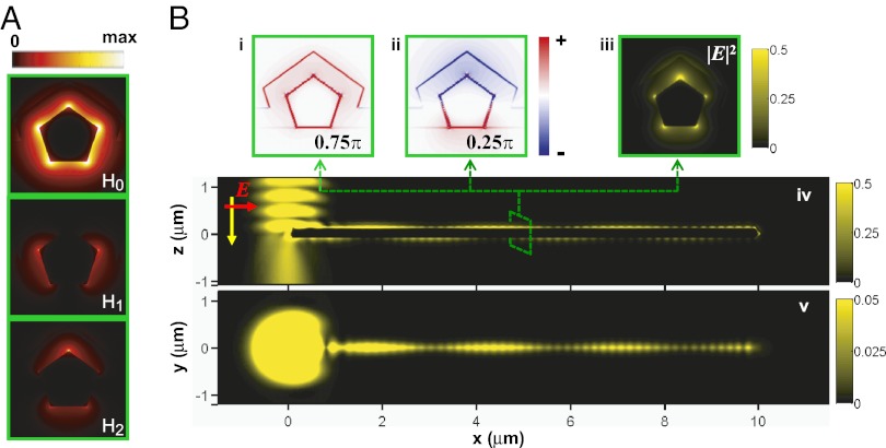
Fig. 2.
Excitation of multiple SP modes on supported NWs. (A) Power distribution of three lowest-order modes on supported NW. (Bi and Bii) Charge plot with different initial phase, 0.75π and 0.25π; (Biii–Bv) electric field intensity |E|2 distribution on different cross-section of the Ag NW, excited by a Gaussian beam at the left end. The yz plot (Biii)/xz plot (Biv) is cut through the wire at x = 5.0 μm/y = 0 μm, and the xy plot is located 10 nm above the coated NW. The radius of the wire is R = 110 nm, and the coating thickness is T = 80 nm. The incident light, λ = 632.8 nm, is polarized parallel to the wire axis in B.

