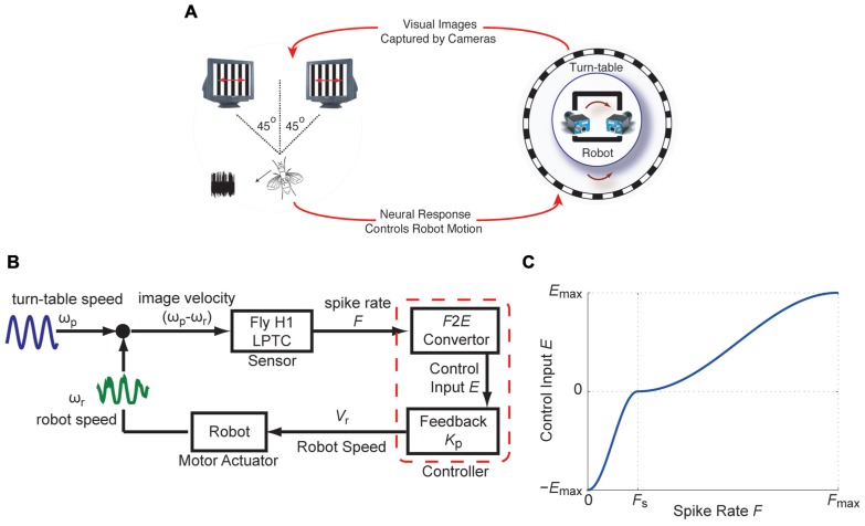
FIGURE 1.
The fly-robot interface (FRI) (A) A fly was placed in front of a visual display consisting of two high-speed CRT displays. Input to the two monitors were provided by two high-speed video cameras mounted on a mobile robot. The robot was positioned on a turntable placed inside a cylindrical arena lined with vertically oriented grating pattern. Robot and turntable movements were limited to rotations around the vertical axis. Visual motion as a result of the rotation of the turntable was captured by the cameras. Electrophysiology recordings from the H1-cell were used to control the rotation of the robot. (B) Block diagram of the closed-loop FRI. Relative motion between the turn-table and the robot, ωp-ωr, caused spiking in the H1-cell. The responses of the H1-cell (instantaneous spike rate F), were used by a controller to compensate for externally generated turntable movements, by driving the robot in the opposite direction. (C) The F2E convertor maps F onto the control input E. The piece-wise sigmoid functions, based on which E was used to update the robot speed Vr. (modified from Ejaz et al., 2012).

