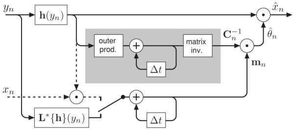
Figure 2.

Circuit diagram for an incremental gSURE2PLS kernel estimator, as specified by equation 5.2 and 5.4b. The quantities mn and Cn must be accumulated and stored internally. The gray box encloses the portion of the diagram in which is computed and may be replaced by a circuit that directly accumulates the inverse matrix, (see appendix A). The entire diagram can also be formulated in terms of the parameter vector, , in place of the vector mn (also shown in appendix A). If supervised data (i.e., clean values xn) are available for some n, they may be incorporated by flipping the switch to activate the dashed-line portion of the circuit (effectively replacing the right-hand side of equation 4.2c by the left-hand side).
