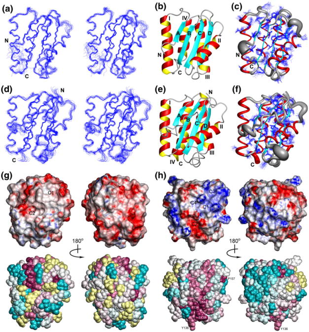
Fig. 1.
a Stereoview of the 20 conformers representing the solution structure of CG2496(41–180) obtained after superposition of the Cα atoms of the regular secondary structure elements for minimal RMSD. Residues 41–52 and 172–180 of the disordered N- and C-terminal polypeptide segments were omitted for clarity, and the termini are labeled as “N” and “C”. b Ribbon diagram of residues 53–171 of the lowest-energy conformer of CG2496(41–180): α-helices are shown in red and yellow, β-strands are depicted in cyan, other polypeptide segments are in gray. c Sausage representation of backbone and superposition of the conformation of the best defined side chains (Table 1). A spline curve was drawn through the mean positions of Cα atoms of residues 53–171 with the thickness proportional to the mean global displacement of Cα atoms in the 20 conformers superimposed in (a). d Same as a for PG0361(35–182) with residues 35–182 shown. e Same as b for PG0361(35–182) with residues 35–182 shown. f Same as (c) for PG0361(35–182) with residues 35–182 shown. g Surface and space-filling representations of the lowest-energy conformer of CG2496(41–180) colored according to the electrostatic potential and the degree of residue conservation, respectively. The default ConSurf color scheme for residue conservation is employed: burgundy for the strongest conservation, cyan for the highest variability, and yellow for residues with insufficient data. Only residues 53–171 are shown with the flexible terminal segments excluded. The structures shown on the left have the same orientation as Fig. 1, and those on the right are rotated by 180° around the vertical axis. Surface clefts identified by Mark-Us/SCREEN are labeled as C1 and C2. h Same as g for the lowest-energy conformer of PG0361(35–182) with residues 35–182 shown, The structures shown on the left are rotated around the vertical axis by 90° relative to the orientation in (d–f), and those on the right are rotated by a further 180°. Surface clefts identified by Mark-Us/SCREEN are labeled as C1, C2, C3 and C4

