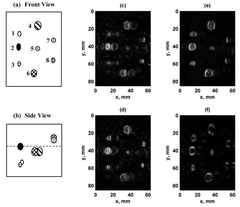
Figure 10.
Images of breast phantom with different configurations. (a) Front view schematic of breast phantom lesions. The lesions are labeled from 1-8. The scale is the same as panels (c)-(f), (b) Side view of breast phantom lesions. The front surface of the phantom corresponds to the top edge of the image, and the dashed line represents the focal plane at zf = 25 mm. (c) Configuration 1, (d) Configuration 2, (e) Configuration 3, (f) Configuration 4. The azimuthal direction of the 1.75D transducer corresponds to the horizontal axis of the image and the mechanical translation of the transducer in the elevation direction corresponds to the vertical axis. [Images in (a) and (b) were adapted from [15]. © 2011 IEEE.]

