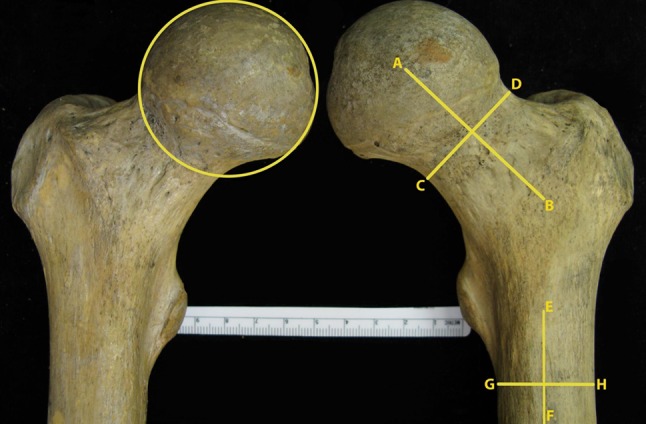
Fig. 1.

An AP view of a pair of femurs is shown. The femoral diameter is shown as the best-fit circle on the femoral head. The minimal neck diameter was defined as the minimal distance about the neck perpendicular to the neck axis. Line AB represents the neck axis. Line CD represents the minimal neck diameter. The shaft diameter was defined as the diameter of a line drawn from the last visible inferior portion of the lesser trochanter tangential to the shaft axis. Line EF represents the femoral shaft axis. Line GH represents the shaft diameter.
