
Figure 4.
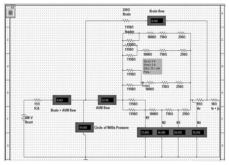
This is an electrical model of a 4-compartment AVM. The resistors simulate the vessels and they are expressed in ohms. The “Heart” is the voltage source and it simulates the human heart. “ICA” -internal carotid artery; “Brain + AVM flow” - flow (in mA) through the brain and AVM complex; “; “Brain flow”- flow through the brain alone; 2 arteries labeled as “feeder” supply each of the 4 nidal compartments; “ dv”-draining vein;” ts+jv”- transverse sinus + jugular vein complex; “N1”-pressure at arterial part of the nidus, “N2”-pressure at the arteriolar part of the nidus, “N3”-pressure at venular part of the nidus, “N4”-pressure at venous part of the nidus. The probe indicates the flow per compartment: “I(dc)”