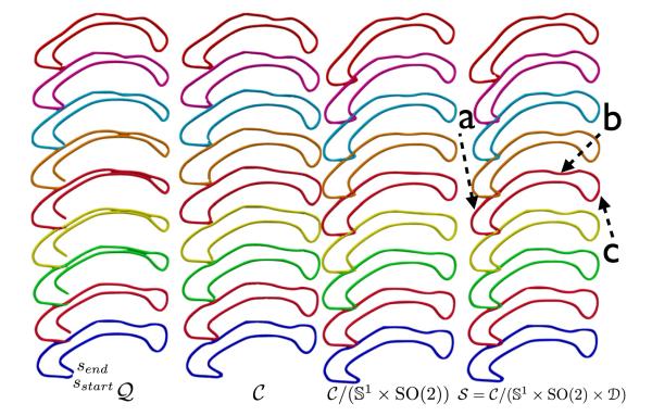
Fig. 4.
Geodesic paths (top to bottom) between two shapes in different pre-shape spaces, and the shape space S. The labeled arrows point to regions where noticeable changes in the shape along the path in S compared to the path in are observed. In the column , start, and send are the end-points of the shape respectively.

