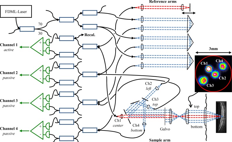
Fig. 4.
JA-OCT interferometer layout. Square boxes represent 3dB fiber couplers, unless the coupling ratio is indicated individually. Fiber based polarization controllers are present in each sample and reference arm (not shown). Note that the direction of view in the sample arm is switched from top view to side view at the galvanometer mirrors in order to better visualize the beam geometry. Inset: Beam profile in front of the eye, with light coupled to all channels. All beams are located in a circular aperture (red) of 3mm diameter.

