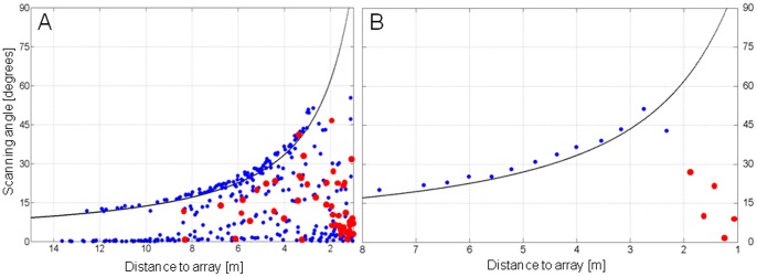
Figure 5. Apparent and real scanning angles.

Apparent and real scanning angles of pipistrelle bats flying towards the microphone array. Angles are measured from the bat’s position and between successive apparent or real beam maxima on the array plane. The black line indicates the calculated maximum angle in the vertical plane that can be measured with the microphone array according to its dimensions and distance from it. (A) Scanning angles of 414 calls measured during 18 flight sequences at the forest and the farm. (B) Scanning angles of a single approach sequence at the farm. Apparent (blue dots) and real (red dots) scanning angles are indicated.
