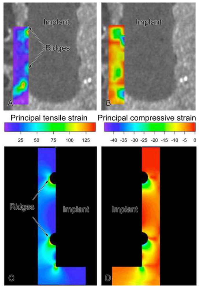
Figure 2.

Contours of principal tensile (A) and compressive (B) strains around a pin-type implant as determined experimentally in a mock interface using DISMAP and micro-CT images. Axisymmetric finite element simulations for groups 1 and 2. For 150 μm motion of a pin implant, tensile and compressive strains of 30–100% were found at strain concentrations (ridges and beneath implant), with lower tensile and compressive principal strains (20%) at smooth sides of the pin. (N.B. The contour plots of tensile and compressive strain as displayed here on the left and right, respectively, should not be interpreted as only indicating strain fields on the left and right sides of the implant; instead in this axisymmetric FE model, one should mentally revolve each strain contour by 360° around the middle vertical axis to construct the strain distribution.).
