
Figure 4.
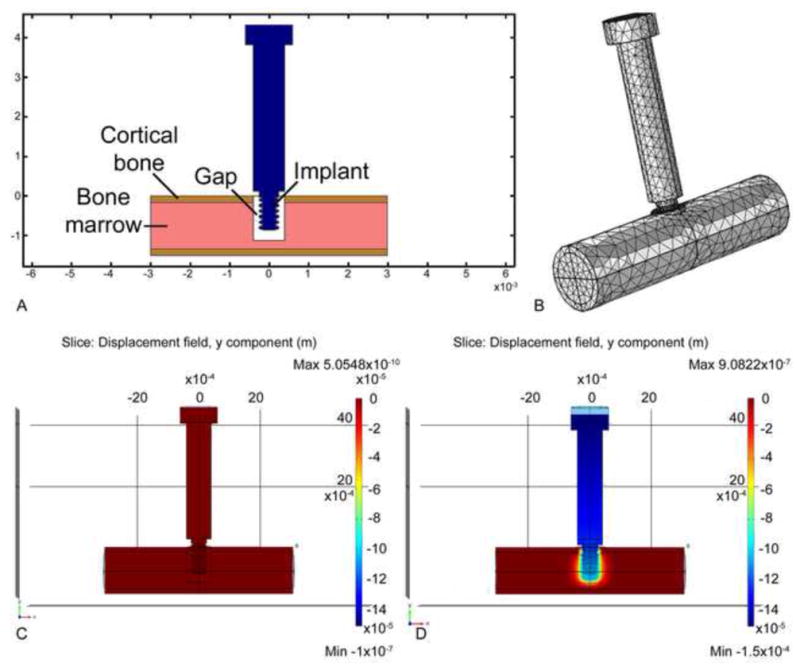
Formulation of a 3-D linear finite element model of the in-vivo situation. Fig. 4A illustrates schematically how the tip of the implant (pin or screw-shaped) resides partly in the cortical region and partly in the marrow region of the mouse tibia. In this illustration a “gap” is shown to depict the situation in the case of a BIGI; mechanical properties for the gap region were determined from our in vivo stiffness measurements (see text). Fig. 4B depicts the 3-D mesh structure for the model. Figs. 4C and D illustrate the displacement of the implant before (C) and after (D) 150 μm of axial downward motion.