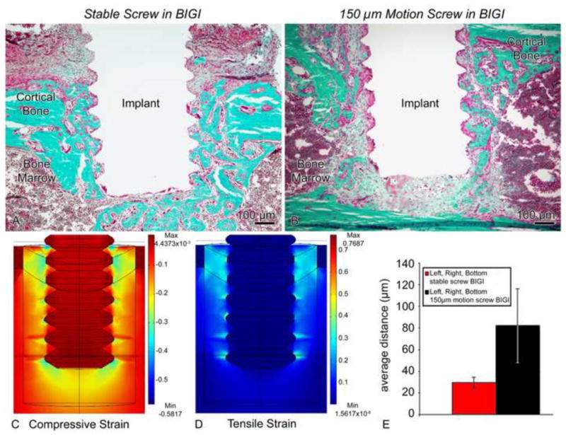
Figure 9.

Light micrographs illustrating the histological appearance of (A) stable (group 5) and (B) screws-shaped implant moving 150 μm in a bone-implant-gap interface (BIGI) (group 6). (A) Bone formation along the interface with the implant is seen in the stable case. (B) However, the strains generated in the loaded implant evidently disrupted bone healing and lead to the formation of a fibrous tissue around the implant. (C, D) Finite element analyses employing day 2 properties for the BIGI (i.e., 6.56 MPa) predicted regions of large (i.e. 30–100%) tensile (C) and compressive (D) principal strains at the tips of the screw threads and beneath the screw. (E) There was a significantly larger bone-implant distance in the motion cases at 7 days co-localizing with these large strains fields (bars show 95% confidence intervals).
