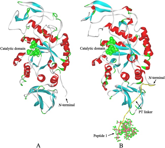
Fig 2.
Structural models of AmyK and AmyK-p1. The α helices and β sheets are shown in red and cyan, respectively. (A) The structural model of AmyK was constructed using the crystal structure of AmyB (3bc9) as a template. The catalytic residues are in green according to the Corey-Pauling-Koltun (CPK) representation scheme. (B) The structural model of AmyK-p1 was constructed using the structural model of AmyK as a template, and molecular dynamics simulations were carried out using the NAMD software with the charmM force field (http://www.ks.uiuc.edu/Research/namd/). The catalytic residues are shown in green according to the CPK representation scheme. The yellow coil is the PT linker. The coil with ball-and-stick residues is peptide 1.

