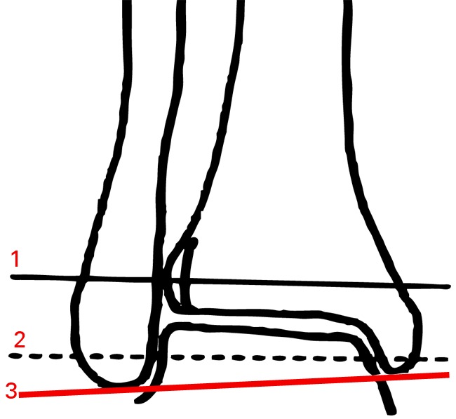
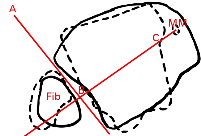
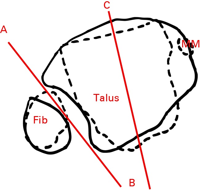
Figs. 4a - 4c.


Figure 4a – diagram of a mortise view showing approximate levels of axial slices shown in the diagrams in Figures 4b and 4c. Line 1 is represented by solid lines and Line 2 represented by dotted lines in Figures 4b and 4c. Line 3 is the line between the tips of the medial and lateral malleoli (intermalleoli line). Figures 4b and 4c – diagrams of superimposed axial slices for b) measurement of the angle (ABC) between the diastasis (AB) and the intermalleoli axis (BC), and c) measurement of the angle (ABC) between the diastasis (AB) and the talus (BC) (MM, medial malleolus).
