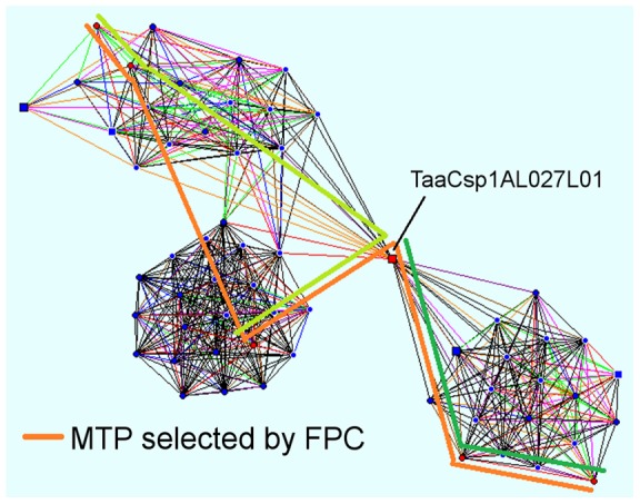
Figure 5. Using Linear Topology to resolve problematic contigs.

Contig205 from the 1AL physical map is represented as a net of significant clone overlaps using LTC software [6], with each vertex representing a clone, and each line a significant overlap between 2 clones. Red circles represent MTP clones, while squares denote clones that have no direct overlap with the MTP. Shapes with a white border denote buried clones. Indicated clone TaaCsp1AL027L01 has multiple significant overlaps with clones in both the left and right halves of the contig, and so has been selected as an MTP clone by FPC (orange bar). However, the fact that no other clones connect the 2 halves of the contig suggest that this may be a chimeric clone, and the contig should be split. Possible MTP routes for the 2 resulting contigs are indicated by the light and dark green bars.
