
Figure 3.
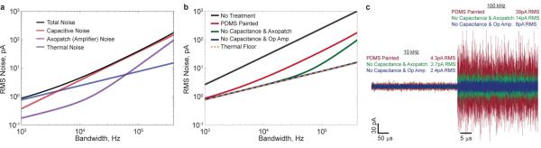
Theoretical calculations of different contributions to nanopore noise. (a) Estimates for individual sources of noise (nanopore resistance, membrane capacitance, and measurement or amplifier), and total RMS noise versus bandwidth obtained from a noise model for PDMS-painted membranes. (b) Estimates for RMS noise versus bandwidth for various device architectures (PDMS-painted, no capacitance and Axopatch, no capacitance and low-noise operational amplifier, and resistive thermal floor). (c) Simulated current traces for different device architectures, providing direct visualization of expected noise reduction from various treatments. The nanopore resistance is assumed to be 30 MΩ. A membrane capacitance of 7.4 pF and dissipation factor of 0.27 are assumed for the PDMS-painted case. The no treatment case reflects a membrane capacitance of 368 pF and dissipation factor of 0.27.