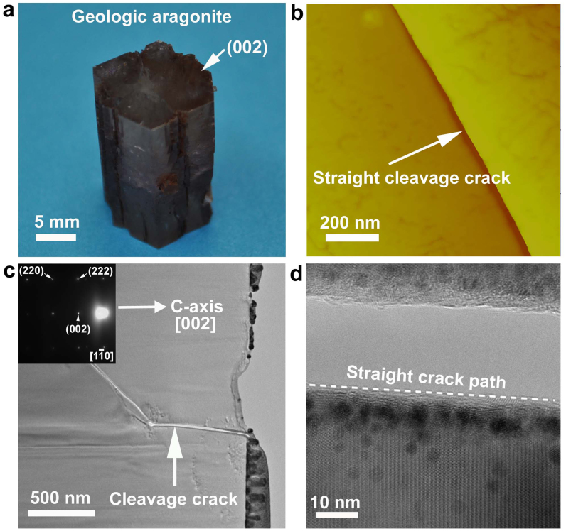
Figure 3. Crack behavior in geologic aragonite monocrystal.
(a), The growth direction of geologic aragonite monocrystal with a pseudo-hexagonal profile on the top surface is toward [002]. (b), AFM observation shows that a representative crack, radiating from the Vickers indentation mark corner on crystallographic plane (002),cleaves aragonite crystal in a straight manner, indicative of brittle fracture mode. (c), A bright-field TEM image reveals crack invasion into the geologic aragonite monocrystal in a cleavage manner, the region around the crack was determined to be single-crystal by diffraction pattern (inset). (d), At the fracture edge, a closer view of lattice fringe exhibits straight crack cleavage behavior, in stark contrast with the intergranular manner within nacre's aragonite platelet. It is worthy pointing out that the “dark” dots around the fracture edge were caused by the unavoidable contamination during the FIB fabrication, i.e. platinum implantation.

