Controlling the size and shape of plasmonic nanoparticles (NPs) is a convenient approach to tune their optical properties for a broad range of applications. For example, metal NPs can function as discrete refractive index elements in optical sensing devices[1] as well as contrast agents in biological imaging.[2] An emerging area in plasmonics that has received less attention, however, is the tailoring of specific structural features of a NP (e.g., sharp asperities) to manipulate their optical properties. Systems of interest that could display signatures of such nanoscale geometrical changes are large (>100 nm) anisotropic NPs because they can support tunable dipole, quadrupole, and higher-order plasmon modes.[3] Although synthetic methods can access different shapes by changing the morphology of the seed (hard) or molecular (soft) templates[4] or by introducing metal ions and other molecules into the growth solution,[5] the overall sizes are usually too small to access higher-order plasmons. One important shape is Au nanorods, which can be grown to various lengths by keeping the width constant and increasing the length[6] or to various widths by preferential overgrowth on their sides.[7] In general, fabrication methods offer a more systematic approach to control different aspects of large particle shapes.[8] Also, the shapes of fabricated NPs tend to have a higher degree of monodispersity because their structures are governed by hard templates (e.g., anodized alumina membranes).[3e, 9]
Fabricated nanopyramidal shells[3f, 10] made from etched single-crystalline Si templates are highly monodisperse (90%) particles that can have variable: 1) base diameters (d = 90–1000 nm) as defined by the size of the photoresist template patterns; 2) composition (Au, Ag, Ni, SiO2) as determined by the materials that can be deposited by e-beam evaporation; and 3) shell thicknesses (t = 15–100 nm). Au nanopyramids support multiple multipolar resonances whose wavelengths are tunable across visible and near IR (NIR) wavelengths.[3b] In addition, pyramidal shells have orientation-dependant resonances, as demonstrated by experiment and confirmed by theory using the discrete dipole approximation (DDA).[3g] Different layers within multilayered Au pyramidal shells (t = 20 nm) can also couple depending on the intershell distances.[11]
An important phenomenological model to describe the optical properties of shell-like particles (in particular, core–shell ones) is plasmon hybridization.[3c] In this scheme, plasmon resonances of the same multipolar order (L) on the inner and outer portions of the thin shells (t < 50 nm) couple to form hybridized bonding and antibonding plasmon modes in a manner analogous to hybridized molecular orbitals.[3c] The resulting hybridized plasmons depend on the dielectric environment, shell-material, and shell thickness.[3c] In the case of nanopyramidal shells, DDA explained how mixed, out-of-plane plasmon excitations because of coupling between the inner and outer shells would disappear with increased shell thickness (from t = 60 nm to t = 100 nm).[3f] Calculations also predicted that progressive tip truncation of pyramids would result in highly controlled red shifts of the quadrupole resonance,[3f] although there has been no verification by experiment.
This paper describes the effects of nanoscale tip truncation on the optical properties of Au nanopyramidal shells. First, the fabrication of tipless (TL) particles with increased amounts of tip truncation using a modified-PEEL method will be described. Next, the scattering properties of TL particles will be presented, and the refractive index sensitivity of the different spectral features will be analyzed. Finally, we will discuss how these plasmon resonances can be interpreted as coupled surface modes based on DDA calculations or hybridized modes using the plasmon hybridization description.
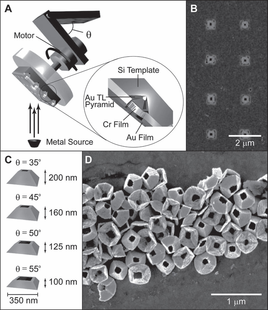
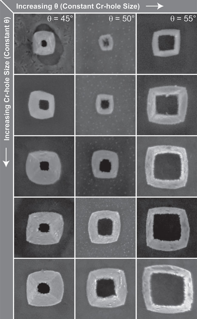
Tipless nanopyramids can be visualized as nanopyramidal shells with an open, square hole instead of a sharp point at the tip.[3f , 12] These structures were fabricated by modifying the third step in PEEL (photolithography, etching, electron-beam deposition, and lift-off),[3g, 10] where the metal deposition was at an angle (θ) instead of line-of-sight (θ = 0°). In brief, a template with a Cr nanohole film on an etched Si wafer was fabricated by phase-shifting photolithography followed by wet chemical etching (the PE in PEEL). The Cr hole diameter was determined by the photoresist post diameter during the P step. This template was then fixed to a custom-built rotational stage fixed at an angle θ that ranged from 35° to 55° (Figure 1A). Next, Au was deposited by e-beam (the second E in PEEL) to a thickness t = 50 nm, and then the Cr nano-hole film was lifted-off (the L in PEEL) using a wet chemical etch. Figure 1B displays highly uniform TL pyramids still embedded in the Si template (θ = 45°). Four representative geometries from deposition θ = 35°, 45°, 50°, 55° with d = 350 nm and particle heights (h) are shown in Figure 1C. The TL pyramids were released from the Si substrate with a combination of isotropic XeF2 etching and sonication in KOH (Figure 1D); notably, the bases of the TL particles were square because of the angled deposition. A wide range of particles sizes and hole openings could be fabricated simply by changing the Cr hole size and deposition θ to produce particles with base sizes in the range of d = 200–620 nm and hole sizes within 70–400 nm (Figure 2).
Figure 1.
Fabrication of TL pyramids. A) Scheme of the modified third step in PEEL, where the e-beam deposition is on a Cr hole array/etched Si template fixed at an angle θ on a rotating stage. B) Scanning electron microscopy (SEM) of θ = 45° TL particles embedded in etched Si pyramidal pits. C) Representative geometries of TL pyramids with base diameter d = 350 nm and calculated particle heights h. D) SEM image of θ = 45° TL pyramids after removal from the Si template.
Figure 2.
SEM images of TL particles with different dimensions. A wide range of hole sizes and particles sizes can be accessed by varying the Cr hole size and/or θ. All images are 850 nm × 850 nm.
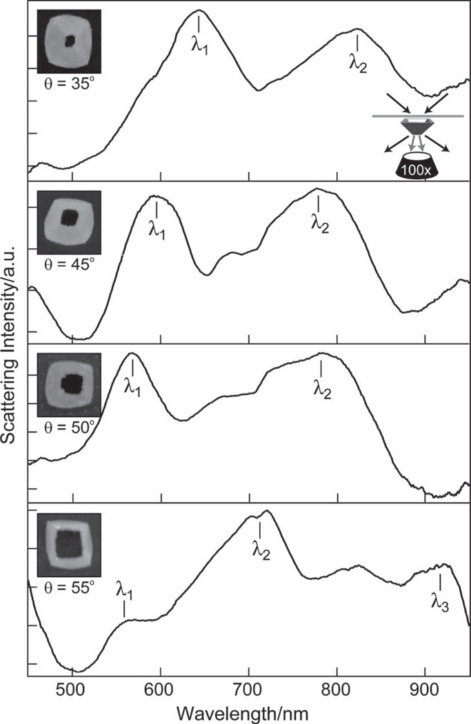
Single-particle dark-field (DF) scattering spectroscopy[13] was used to determine how the amount of tip truncation affected the optical properties of the TL pyramids (Figure 3). We investigated four TL pyramids with deposition angles θ = 35°, 45°, 50°, 55° (also indexed as such) and t = 50 nm. θ = 35° TL pyramids had a height h = 70 nm and showed two distinct resonances in their scattering spectra (Figure 3A). The λ1-resonance at 650 nm was similar to the 600-nm resonance from Au nanopyramids of a similar size and shell thickness (but circular base), where the tip was pointed away from the surface (tip-up orientation).[3f] Notably, the λ2-resonance at 830 nm did not appear in tip-up pyramids. Earlier theoretical work suggested that this λ2-resonance is a coupled mode from the plasmons of the inner and outer surfaces of the TL structure.[3f] For θ = 45°, 50°, and 55° TL pyramids, a resonance analogous to the 600-nm resonance in tip-up pyramids was also observed. These λ1-resonances tended to blue-shift with increased tip truncation; the peak associated with the coupled mode (λ2) also shifted to shorter wavelengths as the hole size increased. Unlike the θ = 35°, 45°, and 50° pyramids, the θ = 55° TL pyramid had a third peak (λ3) at 910 nm. The appearance of this peak seems to emerge because of a large blue shift of the coupled λ2-mode, which then enabled the appearance of a new mode at longer wavelengths.
Figure 3.
Comparison of optical properties of TL pyramids with different θ. Single-particle DF spectroscopy of θ = 35°, 45°, 50°, 55° TL pyramids (d = 350 nm) revealed that the λ1- and λ2-resonances blue-shifted as the deposition angle θ increased. Note the λ3-resonance only appears in the θ = 55° TL pyramid. All spectra were taken in n = 1.65 immersion oil on an indium tin oxide (ITO) substrate (n = 1.8). Insets: SEM images of particles from which spectra were taken. All images are 450 nm × 450 nm.
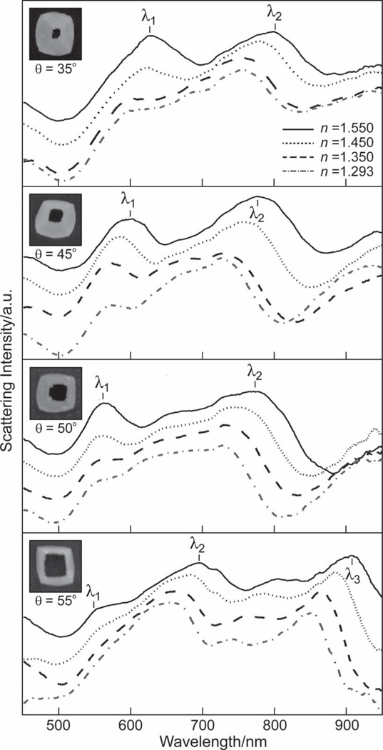
The tunability of the TL particle fabrication enables systematic investigation of the effect of the tip on bulk refractive index (RI) sensitivity. We investigated a range of dielectric media with n = 1.550, 1.450, 1.350, or 1.293. As expected, the resonance of each TL structure red-shifted as n increased (Figure 4). We estimated the RI sensitivity as the slope of the localized surface plasmon (LSP) peak shift (Δλ/Δn) by fitting the λ1-, λ2-, and λ3-resonances to a Lorentzian line shape to determine peak position and full-width at half-maximum (FWHM). The Δλ/Δn and largest figure of merit (FOM) for each resonance is summarized in Table 1, where FOM is defined as:[1b]
| (1) |
Figure 4.
Effect of tip-truncation on RI sensitivity. Single-particle DF spectroscopy of the θ = 35°, 45°, 50°, and 55° TL pyramids in different RI environments (n = 1.550, 1.450, 1.350, 1.293) revealed that the λ1-, λ2-, and λ3-modes red-shifted with increasing n . As expected, the most pronounced shifts occurred in the λ3-resonance of the θ = 55° TL pyramid. Insets: SEM images of particles from which spectra were taken. All images are 450 nm × 450 nm.
Table 1.
RI sensitivities of TL pyramids. The RI sensitivity of the λ1-, λ2-, and λ3-resonances for each TL pyramid was determined by fitting the resonance to a Lorentzian line shape to determine peak position and FWHM. The largest figure of merit (FOM) from one of the resonances (λ1, λ2, or λ3) is shown.
| θ [°]a) | λ1 [Δλ/Δn]b) | λ2 [Δλ/Δn] | λ3 [Δλ/Δn] | FOMc) |
|---|---|---|---|---|
| 35 | 148 | 210 | n/a | 1.7 |
| 45 | 81 | 199 | n/a | 0.8 |
| 50 | 73 | 190 | n/a | 1.3 |
| 55 | 42 | 143 | 210 | 5.7 |
Denotes deposition angle index of TL pyramid;
The slope of the LSP peak for the modes indicated (units in nm/RIU);
FOM determined from Equation 1.
The shortest wavelength resonance (λ1) showed the least Δλ/Δn sensitivity as n was changed; the peak red-shifted with increased n by less than 40 nm in the θ = 35° and 45° TL pyramids, and less than 20 nm in the θ = 50° and 55° TL pyramids. In contrast, the λ2-mode supported a larger red shift of the peak position as n increased, around 50 nm for the θ = 35°, 45°, and 50° TL nanopyramids and 35 nm for the θ = 55° TL nanopyramids. The λ3-resonance was fully resolved in the θ = 55° TL particle and appeared to exhibit the greatest RI response with a FOM of 5.7, a value that is three times higher than any other TL particle and consistent with RI trends for red-wavelength resonances. (Note: the λ3-resonance was not observed in the θ = 35°, 45°, and 50° TL particles). The overall RI sensitivity of the λ1- and λ2-resonances decreased with increased TL particle truncation, falling from 148 nm/RIU to 42 nm/RIU and 210 nm/RIU to 143 nm/RIU, respectively. We propose that this decrease is because the structure of the TL pyramid approaches that of a fl at, thin ring. Structures with a 2D or planar geometry are expected to have lower RI sensitivities[14] compared to 3D ones (e.g., nanostars and nanopyramids), which have sharp features that can support localized electric fields.[15]
A theoretical model using DDA[16] was used to calculate the scattering spectra of a single TL nanopyramid (θ = 35°). TL pyramids were simulated using a multistep process similar to our method used to model pyramids with tips.[3f] For this work, we were more rigorous in matching the experimental TL particle geometry as well as the optical excitation conditions. Since SEM images revealed that the particle had a tapered shell thickness (and not a uniform shell thickness, as in previous cases), we modeled the particles with a 60-nmthick shell at the base and 15-nm thickness at the point of truncation. Additionally, we rounded the square base while keeping d = 350 nm; the effective height h = 202 nm and hole opening = 70 nm. The particle was also placed in a uniform dielectric with n = 1.8. Similar to the experimental DF illuminatiom conditions (15° cone centered at 62.5° from normal), the excitation was modeled such that the wavevector k of the incident plane wave was tilted at 62° from the surface normal.
Classical electrodynamics calculations using DDA were performed to generate the optical spectra. Because this approximation has been employed to describe metal nanoparticles with circular shapes[16b, 17] and for nontruncated pyramidal shells,[3f] we will only discuss here the salient points of the calculation. A TL particle was represented by a square array of point dipoles that obtained an oscillating polarization from the local field, which has contributions from the incident plane wave field and the dipole fields that radiated from all the other dipoles in the array. The dipole polarizability incorporates the optical constants of Au[18] and was assigned based on a lattice dispersion relationship.[19] The set of coupled dipole equations composed a large, dense matrix equation and was solved iteratively to calculate the induced polarizations. These induced polarizations were then used to calculate the scattering cross section, and the procedure was repeated at all wavelengths of interest.
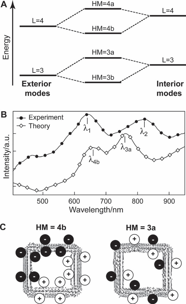
Similar to other large particles,[3b–f, 20] the TL particles have higher-order plasmon modes. The shell thickness is thin compared to the particle size (especially at the truncation point) so that the induced charges on the interior and exterior of each side of the pyramid metal shell interact to form complex plasmon states. We refer to these as coupled surface or hybridized modes (HM) modes. The HM modes in the TL pyramids are analogous to those observed in spherical core–shell nanoparticles, especially those with broken symmetry.[21] Therefore, we use a paradigm similar to the core–shell hybridization model to discuss the experimental results (Figure 5A). The modeled resonances were labeled by multipolar order L (L = 1 for dipole, L = 2 for quadrupole, etc.) and as bonding (b) or antibonding (a). We have assumed locality, where only values with the same L value hybridize, to form the HMs.[22] Although more significant hybridization could occur in the structures because of the 3D morphology,[3c] these plasmon modes will not be addressed here.
Figure 5.
Modeling the optical properties of TL pyramids. A) Plasmon hybridization scheme indicating coupling of the same L modes from exterior and interior particle surfaces. B) Scattering spectra of experiment and theory for θ = 35° TL pyramids. The experimental λ1- and λ2-resonances can be associated with the calculated λ4b bonding and λ3a antibonding plasmonic modes, respectively. C) Vector plots of the induced polarizations for a pyramidal shell nanoparticle (d = 350 nm, tapered shell thickness). The positive and negative charge distributions are highlighted for clarity.
In the calculated spectra, the resonance interactions between modes excited on the interior and exterior surfaces of the TL pyramid were observed at approximately λ4b = 656 nm and λ3a = 762 nm (Figure 5B). The resonances corresponded primarily to an in-plane HM, where the plasmon oscillates parallel to the pyramid base. The vector plots of the induced polarizations (Figure 5C) suggested that the resonance at λ4b = 656 nm is the bonding state (HM = 4b) between interior and exterior L = 4 modes, and the resonance at λ3a = 762 nm is the antibonding state (HM = 3a) between interior and exterior L = 3 modes. Compared to the experimental results, the λ4b-resonance was red-shifted only slightly from λ1 , but the λ3a peak was blue-shifted 60 nm from λ2. Shifts in peak position can be attributed to small structural deviations between the model and actual geometry of the particle, such as slight differences in particle taper or shape of the particle base. By fixing the angle of excitation and accounting for nanoscale feature changes (e.g., tapering), we identified that the spectral features could better be described as hybrid L = 4b and L = 3a modes and not pure L modes; these hybrid modes also blue-shifted with increased tip truncation (data not shown). This description thus improves on our previous work where we predicted that truncated nanopyramids would have pure dipole and quadrupole modes that red-shifted as a result of increased tip truncation.[3f]
In summary, we have shown how control of specific structural features on Au pyramidal shells can enable a methodical investigation of their optical properties. We found that the degree of tip truncation shifted the optical response of TL particles by hundreds of nanometers and produced large blue shifts with decreasing particle height. Although identification of the origin of the plasmonic features is challenging, a combination of DDA and plasmon hybridization methods suggests that the hybrid modes result from coupling between the inner and outer metal surfaces of the TL nanopyramids. More generally, these results indicate that the optical properties in anisotropic geometries can be tailored to achieve desired spectral responses from judiciously designed nanostructures.
Experimental Section
Fabrication of TL Pyramids
TL pyramids were fabricated using a modified PEEL procedure.[10] Briefly, an array of photoresist posts was patterned on a Si(100) wafer by phase-shifting photolithography. Cr was deposited by e-beam (line-of-sight), and the photo-resist was removed with acetone and 1165 photoresist remover (Microchem). The Si was then anisotropically etched through the Cr holes in 6 M KOH at 72 °C to form nanopyramidal pits. The substrate was mounted onto a home-built rotational stage at an angle θ, and Au was deposited by e-beam while the stage was rotated at 800 rpm. The Cr-hole film was then subsequently removed in a Cr etchant (Transene), and the TL pyramids were removed from the Si substrate by a combination of sonication in 6 m KOH etch and isotropic XeF2 etching (Xactix).
Single Particle Scattering Spectroscopy
TL pyramids were dispersed from an aqueous solution onto ITO-coated glass (Delta Technologies, n = 1.80). The ITO substrate was patterned with Au markers through a TEM grid so that TL nanopyramid spectra could be correlated with the TL particle shape determined from SEM images. Particles were immersed in a range of refractive indices (n = 1.650, 1.550, 1.450, 1.350, 1.293) for optical imaging and dark-field spectroscopy using an inverted optical microscope (Nikon TE-2000U) with a halogen light source, a variable NA DF condenser (NA = 0.80–0.95), and a 100× variable NA objective (NA = 0.5–1.3). Single-particle spectra were acquired with a spectro meter equipped with a liquid N2-cooled imaging CCD (Jobin-Yvon).
Acknowledgements
This work was supported by the NSF National Center for Learning and Teaching (NCLT) (ESI-0426328) at the Materials Research Institute, the NSF-MRSEC program at the Materials Research Center (DMR-0520513) at Northwestern University, an NIH NRSA award (1 F32 EB008338-01 A2), and an NSF DMR-1006380 award. This work used the NUANCE Center facilities, which are supported by NSF-MRSEC, NSF-NSEC, and the Keck Foundation.
This Communication is part of the Special Issue dedicated to Chad Mirkin in celebration of 20 years of influential research at Northwestern University.
Contributor Information
Christina M. Sweeney, Department of Chemistry, Northwestern University, 2145 Sheridan Road, Evanston, IL 60208, USA
Christopher L. Stender, Department of Chemistry, Northwestern University, 2145 Sheridan Road, Evanston, IL 60208, USA
Colleen L. Nehl, Department of Chemistry, Northwestern University, 2145 Sheridan Road, Evanston, IL 60208, USA
Warefta Hasan, Department of Chemistry, Northwestern University, 2145 Sheridan Road, Evanston, IL 60208, USA.
Kevin L. Shuford, Department of Chemistry, Drexel University, 3141 Chestnut Street, Philadelphia, PA 19104, USA
Teri W. Odom, Email: todom@northwestern.edu, Department of Chemistry and Department of Materials Science and Engineering, Northwestern University, 2145 Sheridan Road, Evanston, IL 60208, USA.
References
- 1.a) Chamberlin DR, Wang Z, Sultana KA, Chow EK, Sigalas MM, Liu M, Grot AC, Fan S. Proc. SPIE. 2005;5927:592708. [Google Scholar]; b) Sherry LJ, Chang S-H, Schatz GC, Van Duyne RP, Wiley BJ, Xia Y. Nano Lett. 2005;5:2034. doi: 10.1021/nl0515753. [DOI] [PubMed] [Google Scholar]; c) Haes AJ, Zou S, Schatz GC, Van Duyne RP. J. Phys. Chem. B. 2004;108:6961. [Google Scholar]
- 2.a) Hu R, Yong K-T, Roy I, Ding H, He S, Prasad PN. J. Phys. Chem. C. 2009;113:2676. doi: 10.1021/jp8076672. [DOI] [PMC free article] [PubMed] [Google Scholar]; b) Tong L, Wei Q, Wei A, Cheng J-X. Photochem. Photobiol. 2009;85:21. doi: 10.1111/j.1751-1097.2008.00507.x. [DOI] [PMC free article] [PubMed] [Google Scholar]; c) Chen J, Saeki F, Wiley BJ, Cang H, Cobb MJ, Li Z-Y, Au L, Zhang H, Kimmey MB, Li Y, Xia Nano Lett. 2005;5:473. doi: 10.1021/nl047950t. [DOI] [PubMed] [Google Scholar]; d) Loo C, Hirsch L, Lee M-H, Chang E, West J, Halas N, Drezek R. Opt. Lett. 2005;30:1012. doi: 10.1364/ol.30.001012. [DOI] [PubMed] [Google Scholar]
- 3.a) Zhou F, Li Z-Y, Liu Y, Xia Y. J. Phys. Chem. C. 2008;112:20233. [Google Scholar]; b) Lee J, Hasan W, Lee MH, Odom TW. Adv. Mater. 2007;19:4387. [Google Scholar]; c) Wang H, Brandl DW, Nordlander P, Halas NJ. Acc. Chem. Res. 2006;40:53. doi: 10.1021/ar0401045. [DOI] [PubMed] [Google Scholar]; d) Shumaker-Parry JS, Rochholz H, Kreiter M. Adv. Mater. 2005;17:2131. [Google Scholar]; e) Nicewarner-Peña SR, Freeman RG, Reiss BD, He L, Peña DJ, Walton ID, Cromer R, Keating CD, Natan MJ. Science. 2001;294:137. doi: 10.1126/science.294.5540.137. [DOI] [PubMed] [Google Scholar]; f) Shuford KL, Lee J, Odom TW, Schatz GC. J. Phys. Chem. C. 2008;112:6662. [Google Scholar]; g) Henzie J, Shuford KL, Kwak ES, Schatz GC, Odom TW. J. Phys. Chem. B. 2006;110:14028. doi: 10.1021/jp063226i. [DOI] [PubMed] [Google Scholar]
- 4.a) Gole A, Murphy CJ. Chem. Mater. 2004;16:3633. [Google Scholar]; b) Zinchenko AA, Yoshikawa K, Baigl D. Adv. Mater. 2005;17:2820. [Google Scholar]
- 5.a) Hao F, Nehl CL, Hafner JH, Nordlander P. Nano Lett. 2007;7:729. doi: 10.1021/nl062969c. [DOI] [PubMed] [Google Scholar]; b) Jana NR, Gearheart L, Murphy CJ. J. Phys. Chem. B. 2001;105:4065. [Google Scholar]
- 6.Gou L, Murphy CJ. Chem. Mater. 2005;17:3668. [Google Scholar]
- 7.Ni W, Kou X, Yang Z, Wang J. ACS Nano. 2008;2:677. doi: 10.1021/nn7003603. [DOI] [PubMed] [Google Scholar]
- 8.Henzie J, Lee J, Lee MH, Hasan W, Odom TW. Annu. Rev. Phys. Chem. 2009;60:147. doi: 10.1146/annurev.physchem.040808.090352. [DOI] [PubMed] [Google Scholar]
- 9.a) Choi J, Sauer G, Nielsch K, Wehrspohn RB, Gösele U. Chem. Mater. 2003;15:776. [Google Scholar]; b) Qin L, Banholzer MJ, Millstone JE, Mirkin CA. Nano Lett. 2007;7:3849. doi: 10.1021/nl072606s. [DOI] [PMC free article] [PubMed] [Google Scholar]
- 10.Henzie J, Kwak ES, Odom TW. Nano Lett. 2005;5:1199. doi: 10.1021/nl0506148. [DOI] [PubMed] [Google Scholar]
- 11.Lin JY, Hasan W, Yang J-C, Odom TW. 2010:114. [Google Scholar]
- 12.Hasan W, Stender CL, Lee MH, Nehl CL, Lee J, Odom TW. Nano Lett. 2009;9:1555. doi: 10.1021/nl803647n. [DOI] [PMC free article] [PubMed] [Google Scholar]
- 13.a) Nehl CL, Grady NK, Goodrich GP, Tam F, Halas NJ, Hafner JH. Nano Lett. 2004;4:2355. [Google Scholar]; b) Hasan W, Lee J, Henzie J, Odom TW. J. Phys. Chem. C. 2007;111:17176. [Google Scholar]
- 14.Stiles PL, Dieringer JA, Shah NC, Van Duyne RP. Annu. Rev. Anal. Chem. 2008;1:601. doi: 10.1146/annurev.anchem.1.031207.112814. [DOI] [PubMed] [Google Scholar]
- 15.Nehl CL, Liao H, Hafner JH. Nano Lett. 2006;6:683. doi: 10.1021/nl052409y. [DOI] [PubMed] [Google Scholar]
- 16.a) Draine BT. J. Astrophys. Astron. 1988;333:848. [Google Scholar]; b) Draine BT, Flatau PJ. J. Opt. Soc. Am. A. 1994;11:1491. [Google Scholar]
- 17.Yang W-H, Schatz GC, Van Duyne RP. J. Chem. Phys. 1995;103:869. [Google Scholar]
- 18.Johnson PB, Christy RW. Phys. Rev. B: Condens. Matter Mater. Phys. 1972;6:4370. [Google Scholar]
- 19.Draine BT, DGoodman J. J. Astrophys. Astron. 1993;405:685. [Google Scholar]
- 20.Henzie J, Barton JE, Stender CL, Odom TW. Acc. Chem. Res. 2006;39:249. doi: 10.1021/ar050013n. [DOI] [PubMed] [Google Scholar]
- 21.Wang H, Wu Y, Lassiter BL, Nehl CL, Hafner JH, Nordlander P, Halas NJ. Proc. Natl. Acad. Sci. USA. 2006;103:10856. doi: 10.1073/pnas.0604003103. [DOI] [PMC free article] [PubMed] [Google Scholar]
- 22.Park T-H, Nordlander P. Chem. Phys. Lett. 2009;472:228. [Google Scholar]


