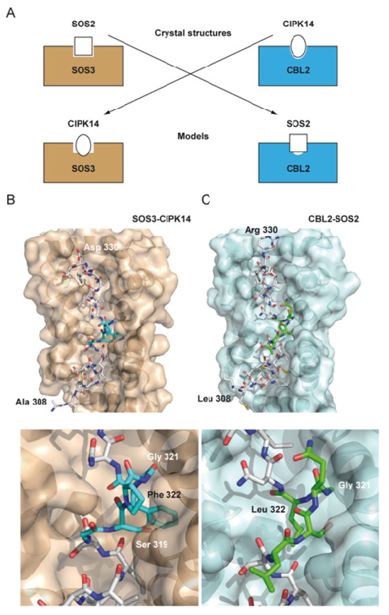
Figure 4.
The specificity of the CBL CIPK interaction. (A) Schematic representation of the modeled complexes. The CIPK14 FISL moiety is inserted into the SOS3 cavity (B) and the SOS2 FISL is inserted into the CBL2 cavity (C). The lower part of the B and C panels represent a zoomed area of the FISL internal loop. SOS3 and CBL2 are displayed as a semitransparent molecular surface. The FISL motives are shown is a stick mode. Those residues form FISL overlapping CBLs are labeled.

