Figure 6.
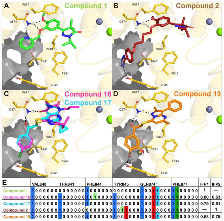
Panels A–D show the TbrPDEB1 backbone as a gold ribbon, key pocket residues and ligands as sticks, metal atoms as spheres, and the P-pocket as a gray transparent surface. The modeled binding poses of compounds 1 (green, panel A) and 2 (red, panel B) are similar to those proposed previously for close analogues,2 and are used as references for the calculation Tanimoto scores based on IFP similarity.21–22 Compounds 16 (magenta) and 17 (cyan) (panel C) show a similar binding mode to compound 1, while compound 19 (panel D) shows a greater similarity to the binding mode of compound 2. Bit strings are used in IFPs to indicate the absence (0) or presence (1) of an interaction type between the ligand and each residue, as shown in panel E for compounds 2, 4, 16, 17 and 18. A sequence of seven bits is used for each residue and the position of each bit determines the interaction type (see legend). For the sake of clarity, only the bit strings of V840, T841, F844, Y845, Q874 and F877 are shown, of the 42 pocket residues.
Protein-ligand interactions described in IFPs are encoded as seven bits per residue as follows: 1. Apolar; 2. Aromatic face-to-face; 3. Aromatic edge-to-face; 4. H-bond donor (protein) – H-bond acceptor (ligand); 5. H-bond donor (ligand) – H-bond acceptor (protein); 6. Ionic interaction positive (protein) – negative (ligand); 7. Ionic interaction positive (ligand) – negative (protein). An additional H-bond bit was included for GLN874 (GLN Filter): * H-bond formation with both polar hydrogen atoms of the Q874 side-chain.

