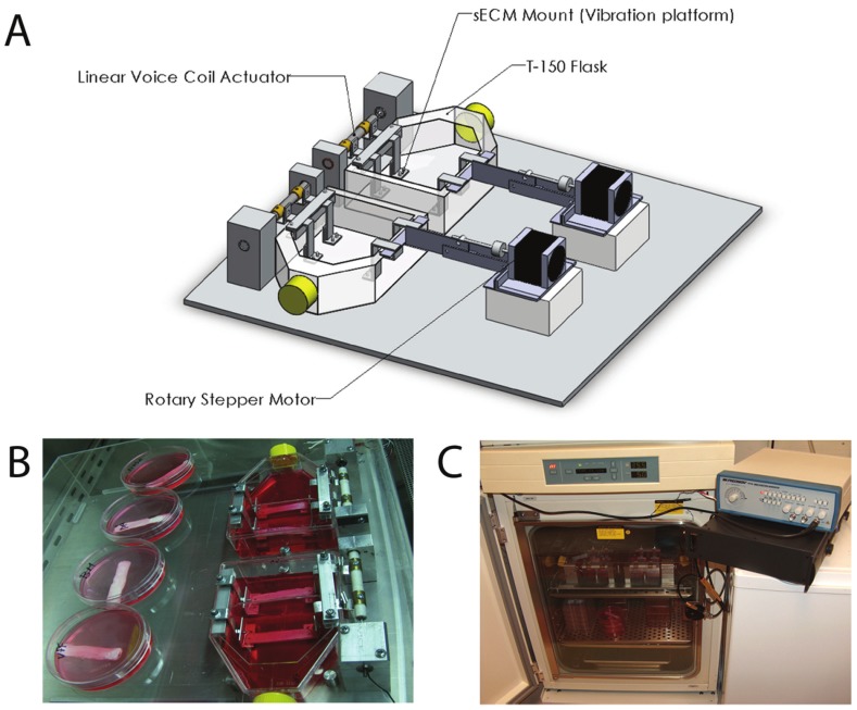
Figure 3.
Schematic of developed bioreactor. A: Bioreactor including T-flask, substrate, voice-coil actuator, linear stepper motors, rotary stepper motors, and scissor bars. B: Experimental setup, with static attachment in place of stepper motors. Non-vibrated controls can also be seen. C: Bioreactor within incubator. Wave-form generator is next to the incubator, sitting on top of the power amplifier. (Reprinted from Gaston J., Rios B.Q., Bartlett R., et al (2011). The response of vocal fold fibroblasts and mesenchymal stromal cells to vibration. PLoS ONE 7(2): p2).

