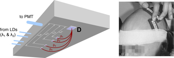
Figure 2.

fNIRS probe. Left: schematic representation of the fNIRS probe, showing four source sites and one detector site (D). Also shown are optical fibers that guide the light from the laser diodes (LD) and the optical fiber that guides light back to the photomultiplier tubes (PMT). l1 to l4: source-detector separations corresponding to light paths p1 to p4. Right: placement of two probes on a subject’s head with adhesive bandages.
