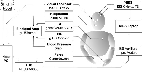
Figure 3.

Schematic representation of the measurement setup. A Simulink® model was used to run the protocol. The physiological signals (blood pressure, SCR, ECG and respiration flow) were amplified and converted with the signal amplifier, which was connected to the host PC via USB. The force applied by the participant was read by the multifunction I/O-card which also sent trigger-signals for synchronization purposes to the NIRS system. The visual output was provided via VGA to the video-goggles worn by the subject. The two NIRS probes were connected to the NIRS oximeter through optical fibers, and data were sent via USB to the NIRS laptop. Ⓒ2011 IEEE. Reprinted, with permission, from [34].
