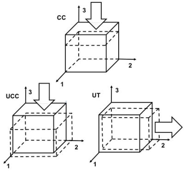
Figure 4.
Displacement boundary conditions for confined compression (CC), unconfined compression (UCC), and uniaxial tension (UT) FEAs. Due to model assumptions (see text), a single element is used with static boundary conditions. The articular surface is defined with outward normal in the +3 direction (i.e. the top surface). Arrows show directions of applied displacements on surfaces with outward normal in the +3, +3, and +2 directions for CC, UCC, and UT, respectively. Reference and deformed configurations are shown as solid and dashed lines, respectively. For CC, surfaces with outward normals in the ±1, ±2, and +3 directions are constrained in the 1 and 2 directions, and surface with outward normal in the −3 direction is constrained in all directions. For UCC and UT, surfaces with outward normals in the −1, −2, and −3 directions are constrained in the 1, 2, and 3 directions, respectively.

