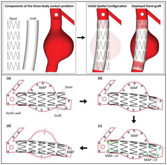
Figure 5.
Schematic representation of components and steps of the deployment of the endograft within the aortic model. (a) Initial spatial configuration of pre-stressed aortic model under mean aortic pressure MAP, unloaded stent, and bent graft following the main curvature of the abdominal aorta. No contact is activated at this time. (b) The stent is crimped, bent, and expanded until contact is established with the graft. At this point, the junctions between stent and graft are enforced by tied contact constraints. (c) The proximal and distal landing zones are expanded via an incremental pressure P to make room for the stent-graft. (d) The incremental pressure P is released and contact between the aortic wall and stent-graft is established. The aneurysm wall contracts slightly in the sac region since it is no longer loaded by the MAP.

