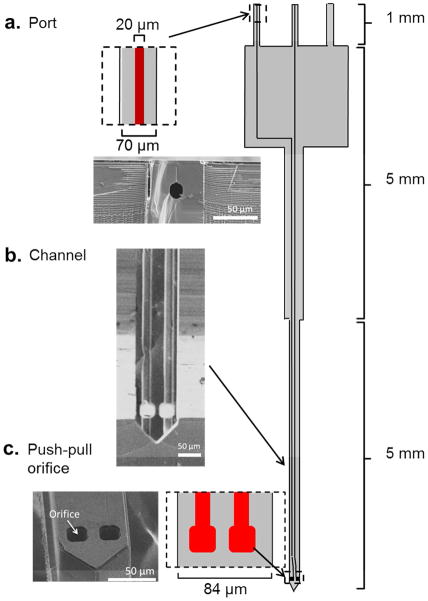
Figure 1.
Layout of probe with scanning electron micrographs of different sections. Drawing at right shows the probe layout. Dark lines in interior are buried channels with 20 μm diameter. (a) Port where connection is made to capillaries. Drawing shows close view and micrograph shows cross section from a probe that was broken to show the buried channel. (Probes had 3 ports. Two were in use for these designs; the third is available for a possible 3rd fluidic arm, but was not used in this work). (b) Micrograph of channel after backside etching to reveal the channels. Slight defect is due to partial unfinished backside etching. (c) Close up drawing and micrograph of the sampling orifice.

