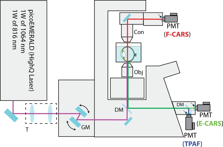
Figure 1.
Schematic diagram of the CARS/TPAF microscope for retina imaging. The copropagating 1064 and 816 nm laser beams were telescoped down (T) and were sent to an Olympus FV-1000 confocal microscope system. The two laser beams were scanned (GM) and focused across the sample by a 60× microscope objective (Obj). The multiphoton signals (CARS and TPAF) were separated from the excitation laser beams with a dichroic mirror (DM). The E-CARS (green) and TPAF (blue) signals were detected by two PMTs in the reverse direction. The F-CARS (red) signal was detected in the forward direction by a third PMTs after the F-CARS signal was collected by a microscope condenser (Con). Dichroic mirrors and emission filter sets (arrows) were used in both epi and forward directions to separate different nonlinear signals spectrally before detection.

