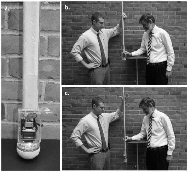
Figure 1.
The clinical reaction time apparatus and testing procedure: (a) the apparatus, (b) pre- drop examiner and test subject positions, (c) post-drop examiner and test subject positions. For the purpose of this illustration, neither the subject nor testing apparatus are instrumented with optoelectronic markers. The light-emitting diode can be seen at far right in (a) as the small light colored hemisphere mounted on the circular shaped transparent plastic top cover to the finger spacer, here seen in side-view.

