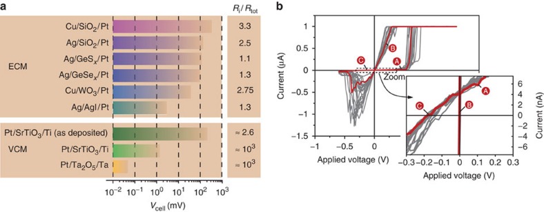
Figure 4. Emf for different types of ReRAM cells.
All tested cells showed an emf varying from some hundreds of microvolts to some hundreds of millivolts (a). The specific steady-state emf depends on the type of cell and the device operation (for example, sweep rate or voltage amplitude before the (open cell) emf measurement). For the sake of completeness, the internal resistance Ri normalized by the total resistance Rtot is given (for details: see Supplementary Table S1). The influence of the emf on the current–voltage sweeps, resulting in non-zero-crossing characteristics (b), is given for the Cu/SiO2/Pt system (red curve) as an example (electrode area Acell=2 × 10⁻⁴ cm2, sweep rate ν=400 mV s−1). The I–V characteristics in grey are provided for statistical verification. For the sake of clarity, the currents of the OFF state (A) and (C) and the ON state (B) are labelled, respectively. The formed valence change memory (VCM)-type cells (Ti/SrTiO3/Pt and Ta/Ta2O5/Pt) show lower emf for the OFF state owing to the higher electronic partial conductivity, that is, higher currents, but lower ion transference number. Emfs for VCM cells are depicted in Supplementary Figs S7,S8, respectively. The I–V characteristics for Ag/SiO2/Pt and Ti/SrTiO3/Pt cells are shown in Supplementary Figs S9,S10.

