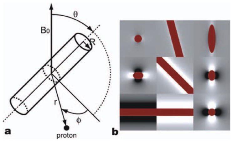
Figure 2.
(a) Summary of radius vectors and angle notations and (b) the field map generated by a single vessel (dark red) in x-y (left), x-z (middle), and y-z (right) planes with three different orientations (θ = 15° (top), 45° (middle), and 90° (bottom)). [Color figure can be viewed in the online issue, which is available at wileyonlinelibrary.com.]

