
Figure 2.
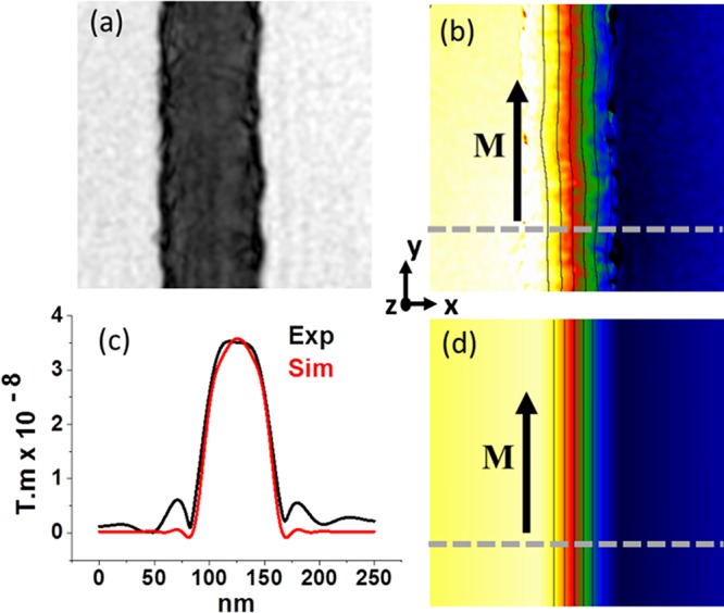
Magnetic phase shift of a uniformly magnetized nanocylinder. Amplitude (a) and (b) magnetic phase shift images in a piece of nanocylinder of 70 nm in diameter without DW. The lines in b corresponds to the isocontour of the phase shift and then to the induction field lines. (d) Calculated magnetic phase shift and isocontour from micromagnetic simulation. The isophase lines in b and d are separated by 0.6 rad. (c) Profile of the modulus of the projected induction in the cross section delimited by the dashed line in b and d.