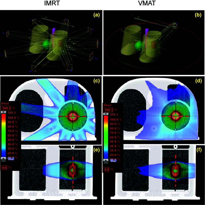
Figure 2.
IMRT (left) and VMAT (right) plan geometries (a) and (d) and dose distributions in [the axial (b) and (e) and sagittal (c) and (f)] planes that contain films. The red dashed lines (lateral and inferior–superior) are the position of dose profiles in Fig. 3.

