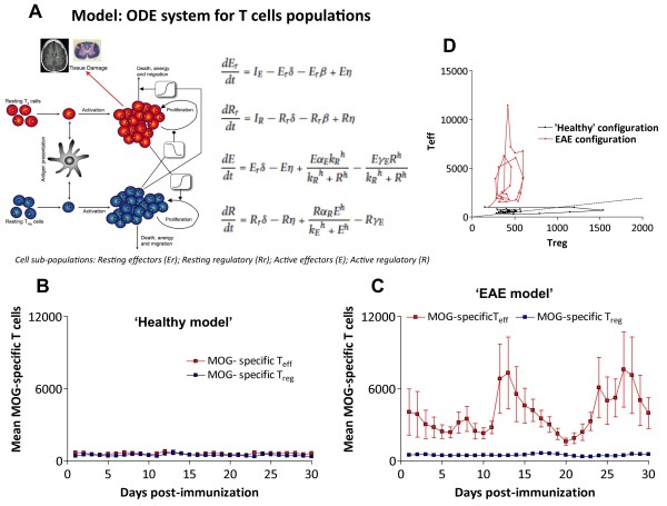
Figure 4.
Simulations from the cross-regulation T-cell model. A) Graphical representation and the equations of the T-cell cross-regulation model as described in [10]. Parameters of the model are described in Additional file 1: Table S1. Simulation of the time course of the number of MOG-specific Teff (red) or Treg (blue) cells in the spleen (y-axis) after immunization (x-axis, in days) by the cross-regulation model in ‘healthy’ (B) and in ‘EAE’ configuration regimes (C). Simulations are shown by mean ± SD of 3 simulations for 30 days (discretized by days) to express average points similarly to experimental data in Figure 2A; D) Phase-space plot shows Teff/Treg trajectories in simulations (30 days) for both configurations (‘healthy’ in black and ‘EAE’ in red).

