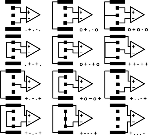
Figure 5.
Recording contact configurations for the mixed design. The connection of each contact is represented by: “.”, if there was no connection; “o”, for short-circuited terminals; and “+” or “-”, indicate the differential amplifier terminal. Dot contacts are represented by squares and ring contacts by strips.

