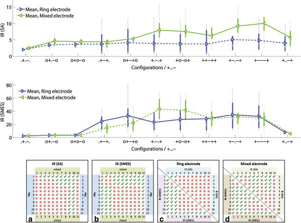
Figure 7.
Improvement ratios (IR). The IR(SA) and IR(SMES) results are presented in box plots where the central mark represents the median value; the edges of the box are the 25th and 75th percentiles; the whiskers give the range of data values; and laterally pointing triangles represent average values. The results for ring and mixed designs are represented in blue and green colors respectively. The IRs were calculated against the outer bipolar configuration, +...-., since this is common to both electrode designs. The statistical significance (p < 0.05) between the configurations in ring and mixed electrodes are shown in a) for SA and b) for SMES, as well as between inter-electrode configurations in c) for the ring electrode, and d) for the mixed electrode. The configuration numbers correspond to the order in which they are presented in the box plots.

