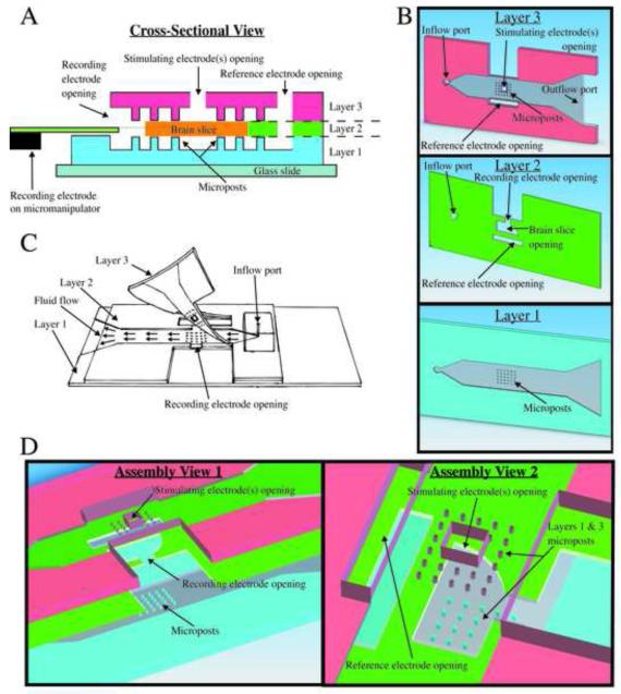
Fig. 1.
Microfluidic perfusion chamber design. (A) A cross-section at the center of the microposts reveals the locations of the electrode openings relative to the brain slice and the different layer features. (B) A computer aided design (CAD) model displays the distinct features from a bottom surface view for each individual layer. (C) A free-hand drawing shows how the device appears after each layer is assembled and how the top layer is partially bonded only at the front. This allows a brain slice to be positioned properly at the electrode openings before the PDMS is temporarily sealed for perfusion to commence. (D) A CAD model shows an exploded three-dimensional view of layers and provides an idea of how alignment of the top and side openings is necessary for the integrity of the chamber.

