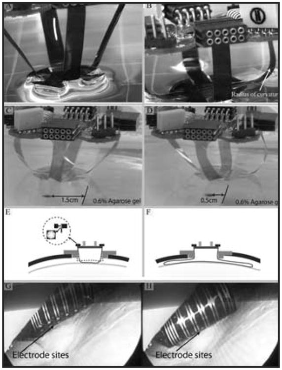
Figure 3.
A) Four legs allow the 2-D array to translate along 3 axes and rotate about an additional 2 axes. The flexible legs maintain only a minimal amount of pressure to ensure close contact between the electrode and tissue. B) The hydrophilicity of the polyimide helps the electrode adhere to the dura or pia mater. C) and D) An x- axis translation of the brain tissue phantom (0.6% agarose gel) up to 1 cm, representing the constant contact of the electrode array with dura due to small brain movement in all x-, y-, z- and 3 rotational axes in vivo. E) A cross-section of the electrode platform shows an assembled electrode and PCB sitting atop a plastic adapter ring inside a craniotomy. The adapter ring can be temporarily fixed to the cranium. The inset shows the multi-leafed electrode contact to the electrical sockets on the PCB. F) Diagram illustrating the flexible legs (longer leg cable than those shown in A-E), which flare out radially under the skull to cover a larger area of cortex. G) and H) Electrode sites come in contact with the dura as the electrode is deployed. The dura can be left intact (pictured) or removed.

