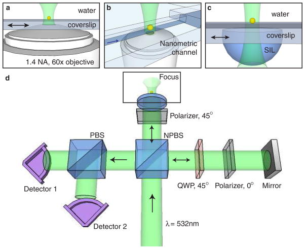
Fig. 1.
The dual-phase detection apparatus. (a) Configuration for immobilized particles. A 1.4 NA oil-immersion objective is used to focus light on a particle, and the particle is scanned through the focus. (b) Nanoscale channel configuration. Particles in solution are loaded into reservoirs at the ends of a 15 μm channel of cross-section 500 nm by 400 nm, and a microscope objective focuses light on the channel. The black arrow indicates the direction of electro-osmotic flow. (c) Numerical aperture increasing lens (NAIL) configuration. A NAIL is water-bonded to a coverslip, and is used to focus light on an immobilized particle, which is scanned through the focus. (d) Schematic of dual-phase interferometer. A linear polarizer sets the polarization state of the signal beam to 45°, and a combination of a polarizer and quarter-wave plate (QWP) set the reference polarization to be circular. After reference and signal are combined with a non-polarizing beamsplitter (NPBS), a polarizing beam-splitter (PBS) sends the two orthogonal polarization states to detectors. The difference in relative phase between signal and reference at the two detectors is π/2.

