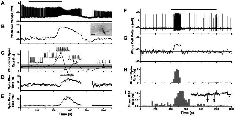
Figure 3. Whole-cell recording of mitral cell voltage response to CCK-8S stimulation.
A. Whole-cell current clamp recording of membrane potential change of a mitral cell during perfusion with 1 µM CCK-8S (bar indicates 400 s period of switched perfusion) showing elevated firing correlated with a slow depolarizing potential of ∼16 mV amplitude. B. Slow depolarizing response revealed by applying low pass filter (0.10 Hz) to trace in A. Inset image: biocytin stain of recorded cell showing amputated apical dendrite (scale bar: 50 µm). C. Plot of windowed spike rate vs. time for response in A, showing several phases of spike excitation and suppression (e 1, s 1, e 2, s 2). All spike events were counted, including those with reduced amplitude (but doublets only once). The first suppressive phase (s 1) correlated with a period of spike inactivation at depolarization peak, the second (s 2) with a post-stimulus hyperpolarization. Inset traces: 1 s expanded segments of voltage record at different times (arrows): basal spike rate (200 s), rising phase (430 s), first peak (500 s), first minimum (570 s), second peak (650) and recovery (1000 s). D–E. Running average plots of spike rise times (D) decay times (E) for the response in A (mean ± standard deviation, in 10 s bins). F. Whole-cell current clamp recording of membrane potential from a second mitral cell with a spiking response to 1 µM CCK-8S perfusion (horizontal bar). G. Slow depolarizing response revealed by applying a low pass filter (0.10 Hz) to trace in F. H. Histogram of spike counts over time (20 s bins) for the trace in F. I. Histogram of IPSP counts over time (20 s bins) for the trace in F. Inset: expanded trace from F showing action potential and IPSPs (arrows) occurring during the CCK response.

