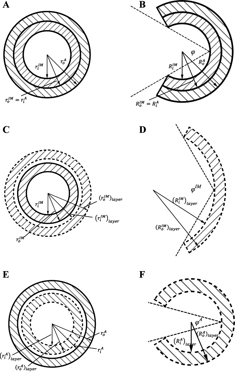
Fig. A1.
Schematic representation is shown of an intact vessel wall at no-load or loaded states (A) and zero-stress state (B). Schematic representation is shown of a single intima-media layer at no-load or loaded states (C) and zero-stress state (D). Schematic representation is shown of a single adventitia layer at no-load or loaded states (E) and zero-stress state (F). The solid lines refer to the measurements in an intact vessel wall, while the dash lines refer to those in a single layer, intima-media layer (forward slashes), or adventitia layer (backward slashes). See text for definition of terms.

