
Figure 2.
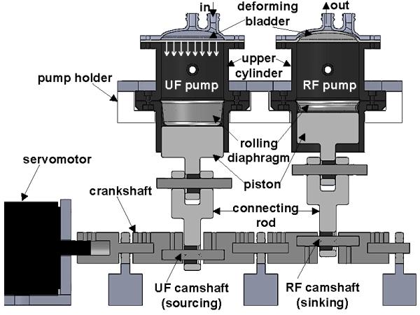
Schematic showing the conservation of volume fluid balance (FB) method implemented via crankshaft-based mechanical coupling of ultrafiltrate (UF) and replacement fluid (RF) pumps. The UF pump is shown in sourcing position and RF in sinking position, with the inflow/outflow ports indicated. The next half of the pumping cycle results in UF sinking and RF sourcing. An approximate indication of the position of the deforming bladder is shown for both pumps, along with the direction of UF pump bladder motion.