
Figure 5.
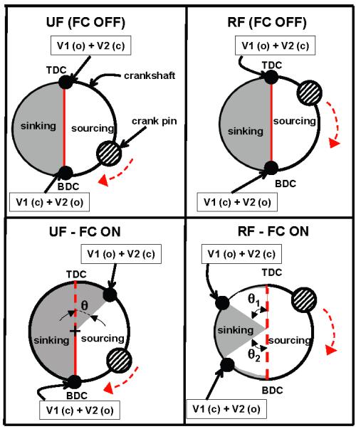
Crank circle diagram for illustrating flow control technique employed in UF and RF pumps in KIDS CRRT device via manipulation of valve timing. The top panels are for the nominal (no flow control) case and the bottom panels show the flow control implementation. The shaded regions are used for sinking phase of the pump cycle.