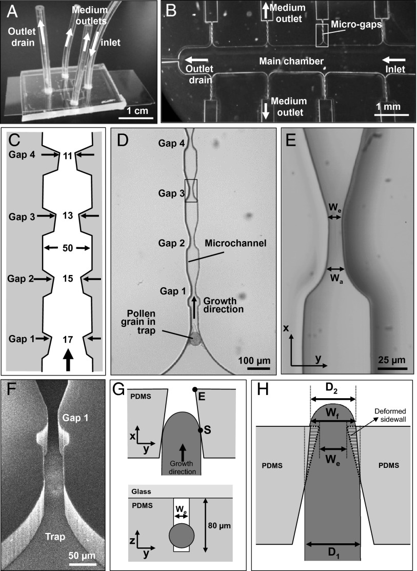
Fig. 1.
Experimental setup for the exposure of pollen tubes to microgaps and geometry of interaction. (A) Macro photograph of the TipChip illustrating arrangements of inlet and outlets. (B) Micrograph showing the geometry of the microfluidic network. (C) Dimensions of the microchannel with repeated narrow regions (microgaps). Numbers are in micrometers; the drawing does not reflect the aspect ratio. (D) Bright field micrograph of the geometry of a microchannel comprising the channel entrance with a trapped pollen grain and four subsequent gaps. (E) Close-up micrograph of a microgap indicated in D, showing an opening with Wa and We. (F) Scanning electron micrograph of the entrance of a microchannel and the first microgap viewed from an oblique angle. (G) Simplified schematic views of the interaction between an elongating pollen tube (dark gray) and a microgap. The pollen tube initially is in contact with both tapered sidewalls forming the microgap at point S. The microgap is formed as a rectangular, slit-shaped opening (white) in the PDMS material (light gray). (H) The passing pollen tube deforms the PDMS sidewalls of the gap to change the gap width at the narrowest section from We to Wf. During passage through the gap, the original width of the pollen tube D1 temporarily is reduced to D2 but typically widens after passing the gap.

