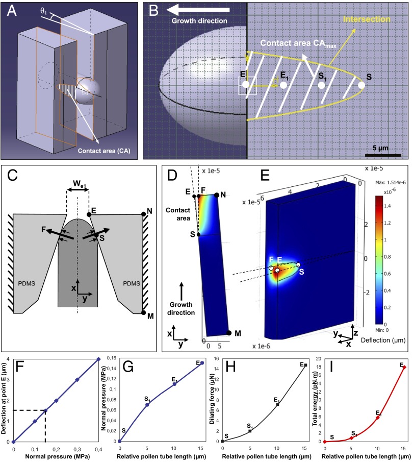
Fig. 4.
Finite element model for the simulation of force exertion by the pollen tube on the sidewalls of the microgap. (A) Three-dimensional representation indicating the contact surface between the pollen tube and microgap when the pollen tube is in maximum contact with the sidewall. (B) Position of four reference points on the contact area, starting with point S upon initial contact and ending with point E, the exit of the gap. Points S1 and E1 are two sample points equally spaced between S and E. (C) Top view of the simulated geometry, indicating the orientation of the force vectors. (D and E) Top view (D) and 3D view (E) of sidewall deflection at effective pressure P = 0.15 MPa. The color code represents the deflection of the PDMS material. (F) Effect of varying effective pressure on sidewall deflection at point E as simulated by the finite element model. (G) Normal pressure required for sidewall deformation during pollen tube passage through the gap. (H) Dilating force F required for sidewall deformation during pollen tube passage through the gap. (I) Total energy required for sidewall deflection during pollen tube passage through the gap. (G–I) The values are plotted as a function of the pollen tube length, measured relative to the initial length of the tube at the moment of first contact with the microgap wall.

